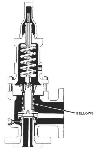
Balanced Bellows Relief Valves
Balanced type relief valves consist of spring-loaded valves which contain a bellows arrangement to keep back-pressure from affecting the set point. The picture above shows a balanced bellows relief valve diagram. The bonnet is vented to atmosphere and a bellows is installed so that the back-pressure acts both downward and upward on the same area of the disc.
Balanced bellows relief valves are typically used where the relief valves are piped to a closed flare system and the back-pressure exceeds 10% of the set pressure which can’t be handling by conventional relief valves. They balanced bellows relief valves also used in flow lines, multiphase lines, or for paraffinic or asphaltic crude which may plug the pilot-operated valves.
Categories: Pressure Relief | Tags: Balanced bellows, pilot-operated valves, relief valves | Leave a comment

