Dispersed Gas Units Separator
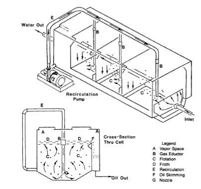
A vortex set is used to disperse gas bubbles in the stream on dispersed gas units. The figure above shows a dispersed gas units with hydraulic eductor schematic. Clean water from the effluent is pumped to a recirculation header (E) that feeds a series of venturo eductors (B). Water flowing through the eductor sucks gas from the vapor space (A) that is released at the nozzle (G) as a jet of small bubbles. The bubbles rise causing flotation in the chamber (C) forming a froth (D) that is skimmed with a mechanical device at (F).
The hydraulic eductor units use less power and less gas than mechanical rotor units. Gas – water ratios are less than 10 ft2/bbl. The gas volume dispersed in the water is not adjustable, so through puts less than design results in higher gas/water ratios.
The figure above shows a diagram of a dispersed gas flotation cell that uses a mechanical rotor. The rotor creates a vortex and vacuum in the vortex tube. The shrouds assure that the gas in the vortex mixes with and is entrained in the water. The rotor and draft inducer causes the water to flow as indicated by the arrows in this plane while also creating a swirling motion. A baffle at the top directs the froth to a skimming tray as a result of this swirling motion.
Typical dispersed gas units consist of three or four cells. Bulk water flows in series from one cell to the other by underflow baffles. The flow will be plugged on high intensity of mixing in each. Therefore, there is virtually no short circuiting or breakthrough of a part of the inlet flow to the outlet weir box.
Categories: Oil and Gas Separator | Tags: Dispersed Gas Units, hydraulic eductor, venturo eductors | Leave a comment

